When it comes to selecting materials for PCBs, FR-4 is often mentioned. Strictly speaking, FR-4 is not the name of a material but rather a flame retardancy grade.

FR-4 PCB
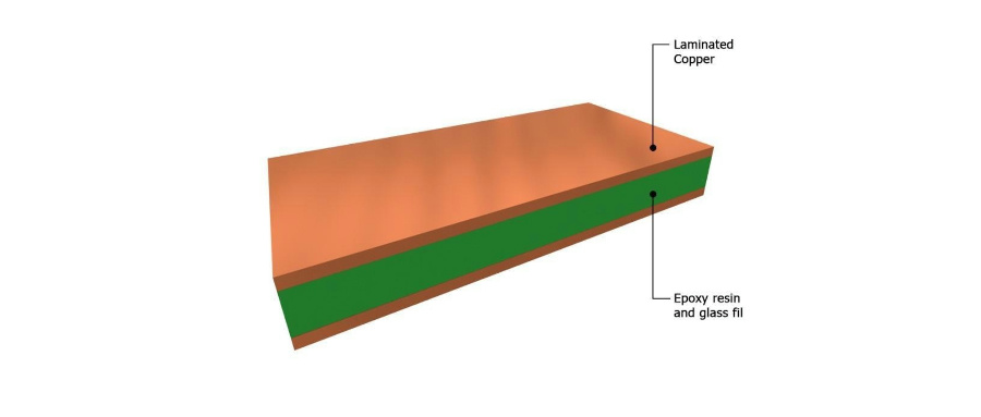
The specification standard for FR-4 is set by NEMA (the National Electrical Manufacturers Association). In NEMA's classification, FR stands for Flame-Retardant. FR-4 indicates a board with an epoxy resin base and glass fiber cloth reinforcement, with a flame retardancy grade of UL94 V-0.
Currently, there are many types of FR-4 grade materials used in circuit boards, most of which are composites made from a four-functional epoxy resin with fillers and glass fiber.
Different FR-4 Materials and Their ApplicationsThe base material of the PCB varies, and so does the flame retardancy grade, which is divided as follows:
Phenolic paper-based boards use phenolic resin as a binder, with wood pulp fiber paper as the surface reinforcing material. XPC, XXPC are non-flammable types, while FR-1, FR-2, FR-3 are flame retardant types. They are cost-effective and mainly used in products like toys, radios, telephones, and calculators.
Commonly known as epoxy boards, fiberglass boards, or fiber boards, these are made with epoxy resin as the binder and electronic-grade glass fiber cloth as the reinforcing material. FR-4 and FR-5 are both flame retardant types.
The CEM series of copper-clad laminates, with CEM-1 and CEM-3 being common examples, are positioned between epoxy-glass fabric-based boards and phenolic-paper-based boards in terms of mechanical properties and manufacturing costs.
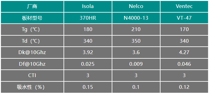
The performance indicators for FR-4 substrates include the glass transition temperature (Tg), the thermal decomposition temperature (Td), the dissipation factor (Df), the dielectric constant (Dk), the comparative tracking index (CTI), the thermal expansion coefficient (CTE), the water absorption rate, and the material's adhesion characteristics.
Taking Isola, Nelco, and Ventec's FR-4 boards as examples:

The Tg value refers to the temperature at which the material transitions from a relatively rigid "glass" state to a deformable state. As long as the thermal decomposition temperature (Td) is not reached, this thermodynamic change is reversible, and the material can return to a rigid state when cooled below the Tg value. When the temperature exceeds the thermal decomposition temperature, FR-4 will decompose and fail.
The industry typically classifies FR-4 boards into three categories based on the Tg value:
Low Tg FR-4: Tg around 135°C;
Mid Tg FR-4: Tg around 150°C;
High Tg FR-4: Tg around 170°C.
If the PCB processing involves many lamination cycles, has many layers, high soldering temperatures (≥230°C), high operating temperatures (over 100°C), or significant soldering thermal stress (such as wave soldering), high Tg boards should be chosen.
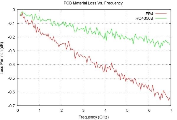
The dielectric constant and the dielectric loss angle are two fundamental properties of a medium. These two parameters change with frequency, and the larger the dissipation factor (Df), the greater the attenuation. The dielectric constant (Dk) has a greater impact on impedance.
FR-4 can be divided based on the dissipation factor (Df):
Normal dissipation boards: Df ≥ 0.02
Medium dissipation boards: 0.01 ≤ Df < 0.02
Low dissipation boards: 0.005 ≤ Df < 0.01
Ultra-low dissipation boards: Df < 0.005

The Comparative Tracking Index (CTI) is used to measure the electrical tracking (tracking breakdown) performance of insulating materials. Tracking occurs on the surface of the insulating material, where heat generated by dielectric loss causes the dielectric to heat up, decompose, and carbonize, eventually leading to a short circuit between the electrodes.
The CTI value of a material is directly proportional to its insulating performance. A higher CTI value means that the required creepage distance can be shorter, allowing closer spacing between two conductors.

For products used in high-voltage, high-current working conditions, such as in aircraft and ships, where high insulation requirements are needed, an FR-4 board with a higher CTI can be chosen.
Despite its low cost, good processability, stable electrical properties, high mechanical strength, and heat resistance, FR-4 shows its limitations in high-speed, high-frequency, and high-power applications.
As the signal propagation speed increases and the distance lengthens, the internal transmission loss of the signal must be considered during layout.

The dissipation factor (Df) of FR-4 is about 0.020, while most high-speed board materials have a Df value of about 0.004, which is only one-fourth of FR-4's Df value. The smaller the Df value, the smaller the signal propagation loss.
The dielectric constant (Dk) affects the impedance of PCB traces. Discontinuity in impedance can lead to signal overshoot, reflection, and ringing. The dielectric constant (Dk) also changes with frequency. The deviation of FR-4 material parameters can reach up to 10%, while high-speed materials can be controlled to 2%.
During the thermal design phase of a product, the thermal design of the PCB is also a key factor. How to design the heat dissipation path? What is the thermal conductivity of different materials? These factors need to be considered.
FR-4 should not be exposed to high temperatures for extended periods as the board can deform. For example, the processing temperature of lead-free reflow soldering can reach up to 250°C, which is higher than the Tg value of many FR-4 boards. The stress caused by the thermal expansion and contraction of the substrate can lead to solder joint fractures, soldering defects, and other issues. Special attention should be paid to selecting a board with a low expansion coefficient when components larger than 3.2×1.6mm are present on the PCBA.
Note: The above content is collated from the Internet, and the copyright belongs to the original author. If there is any infringement, please contact us for deletion.