
From millimeter-wave radar to 4D millimeter-wave radar
Among various sensors, millimeter-wave radar has been widely used in autonomous driving due to its advantages of small size, low cost, all-weather operation, speed measurement capability, and high distance resolution. However, traditional millimeter-wave radar (also known as 3D millimeter-wave radar) has poor performance in measuring target height (3D radar is not unable to measure height, but the resolution is relatively poor), and usually only contains distance, azimuth, and speed information. In addition, 3D millimeter-wave radar has problems such as clutter, noise, and low resolution, especially in the angular dimension, which ultimately limits its applicability in complex perception tasks.
The advancement of multiple-input multiple-output (MIMO) antenna technology has improved the resolution of elevation angle, leading to the emergence of 4D millimeter-wave radar. 4D millimeter-wave radar can measure four types of target information: distance, azimuth, altitude (elevation angle), and speed, making it possible to:
The longest detection distance can reach more than 300 meters, which is longer than that of laser radar and visual sensors;
The horizontal angular resolution is high, usually reaching an angular resolution of 1, which can distinguish between two nearby cars at a distance of 300 meters;
It can measure pitch angle with an angular resolution of better than 2°, and can distinguish between ground objects and overpasses at a distance of 150m;
When there are crossing vehicles and pedestrians, high-precision horizontal angles and high-precision pitch angles can effectively identify targets when the Doppler is zero or very low;
The target point cloud is denser and richer in information, making it more suitable for integration with deep learning frameworks.
4D millimeter-wave radar is expected to occupy the niche of laser radar after cost reduction on mid-to-low-end models, forming a cost-effective intelligent driving hardware combination with cameras and traditional millimeter-wave radar.
Disassembly of ZF 4D millimeter-wave radar products
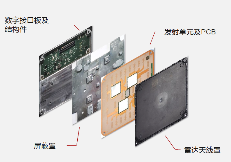
ZF's 4D millimeter-wave radar is applied on a mid-to-high-end pure electric platform in China. Each vehicle is equipped with two radar units, which are installed inside the front and rear bumpers, achieving a maximum detection distance of 350 meters. From the disassembled information, the 4D radar can be divided into four parts, namely the digital interface board and structural parts, the transmitting unit and PCB, the shielding case, and the radar antenna cover, as shown in the figure below.
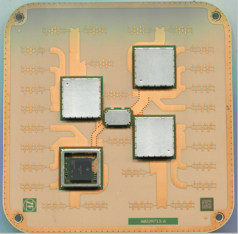
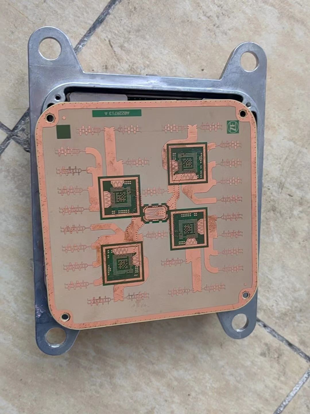
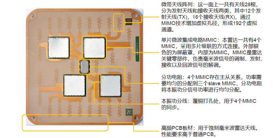
The radar has four MMICs (monolithic microwave integrated circuits) connected in a cascade manner. The silver-colored external part is the shielding case, and the internal part is the MMIC. The MMIC is a key component of the radar, which completes the modulation, transmission, reception, and demodulation of the radar transmission signal. The four MMICs have a master-slave relationship, and the power needs to be evenly distributed to the three slave MMICs. The power distribution resistor evenly distributes the local oscillator power distribution signal power. The local oscillator power distribution line at the copper-clad punching site is used for synchronization of the four MMICs. The high-frequency PCB board has higher performance requirements than ordinary PCBs, and is mainly used for etching millimeter-wave radar antennas. The detailed structural diagram is shown below.
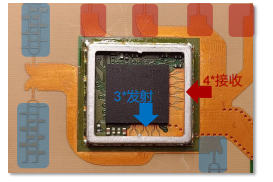
After removing the shield, the black MMIC inside can be clearly seen, as well as the 3-out-4-in circuit characteristic, as shown in the following image. The specific model of the MMIC is AWR2243P, provided by Texas Instruments.
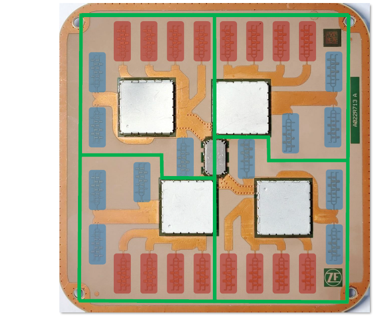
From the perspective of radar antenna arrangement, the difference between 4D millimeter-wave radar and traditional millimeter-wave radar can also be distinguished. In the figure below, the upper part is the dismantled ZF 4D millimeter-wave radar. Interested friends can study this antenna layout (sparse uniform array + Monopulse layout) on their own. The lower part is a traditional 3D millimeter-wave radar from Denso in Japan.
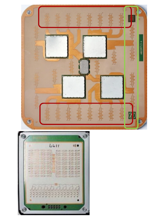
Azimuth angle detection is calculated by the phase difference of the signals received by the receiving antenna. The horizontally aligned receiving antenna can detect the phase azimuth angle information in the horizontal direction (red box in the figure above). The transmitting antenna in the light green box and the receiving array in the red box form a virtual aperture array in the vertical direction through MIMO technology to achieve height measurement, which can obtain the height information of the target (green box in the figure above). As a comparison, the traditional millimeter-wave radar transmitting antenna and receiving antenna only arrange the antennas horizontally, and there is no layout of transmitting or receiving antennas in the height direction, so it cannot detect height information.
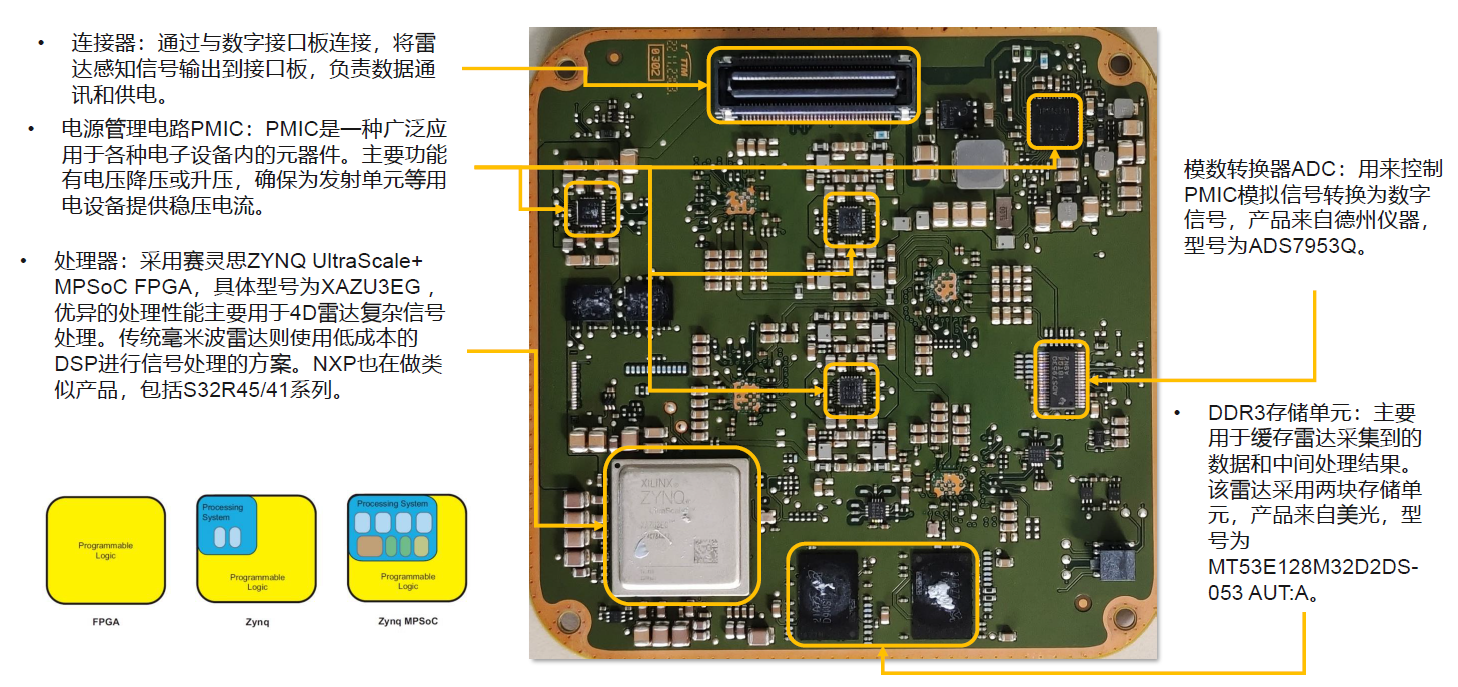
The opposite side of the transmitting unit has a connector, a power management circuit PMIC, a processor, an analog-to-digital converter ADC, and a DDR3 storage unit.
The connector is connected to the digital interface board to output radar sensing signals to the interface board and is responsible for data communication and power supply. The power management circuit PMIC is a widely used component in various electronic devices. Its main functions include voltage bucking or boosting, ensuring stable voltage and current for power-consuming devices such as transmitting units.
The processor uses Xilinx Zynq UltraScale+ MPSoC FPGA, with the specific model being XAZU3EG. Its excellent processing performance is mainly used for complex signal processing in 4D radar. Traditional millimeter-wave radar uses low-cost DSP for signal processing. NXP is also working on similar products, including the S32R45/41 series.
The analog-to-digital converter ADC is used to control the conversion of PMIC analog signals into digital signals. The product is from Texas Instruments and the model is ADS7953Q. The DDR3 storage unit is mainly used to cache the data and intermediate processing results collected by the radar. The radar uses two storage units, which are from Micron and the model is MT53E128M32D2DS-053 AUT:A.
The digital interface board and structural components consist of CAN FD interfaces, heat sink fins, Ethernet interfaces, and digital interface boards. Traditional millimeter-wave radar has a small amount of data, estimated at 20Hz, with a data volume of approximately tens of kbps. CAN FD supports up to 5Mbps, which is sufficient to support its data transmission requirements.
The large power of 4D millimeter-wave radar (about 25W) results in a large amount of heat generation. The cooling fins on the back of the structural parts help dissipate heat and reduce its operating temperature. The number of point clouds of 4D millimeter-wave radar has been greatly increased, reaching hundreds or even thousands of point clouds, and the high data transmission rate of Ethernet can support its transmission requirements. The digital interface board is responsible for adapting and transferring signals and power between the radar and the vehicle domain control. The details are shown in the figure below.
PCB design and material usage for millimeter-wave radar
Millimeter-wave radar mostly uses complete single-chip solutions such as TI, Infineon, or NXP, which integrate RF front-end, signal processing unit, and control unit on-chip, providing multiple signal transmission and reception channels. There are mainly the following methods for designing the PCB board of the radar module:
Using ultra-low loss PCB materials as the carrier board for the top-level antenna design, the antenna design typically uses microstrip patch antennas, with the second layer of the stack serving as the ground for the antenna and its feed line. Other PCB materials in the stack are all made of FR-4 materials. This design is relatively simple, easy to process, and low cost. However, due to the thin thickness of ultra-low loss PCB materials (typically 0.127mm), attention needs to be paid to the impact of copper foil roughness on loss and consistency. At the same time, the narrow feed line of the microstrip patch antenna requires attention to the line width accuracy control during processing.
Using dielectric integrated waveguide (SIW) circuits instead of microstrip patch antennas for radar antenna design. In addition to the antenna, other PCB laminates use FR-4 material as the radar control and power layers. The SIW antenna design still uses ultra-low loss PCB materials to reduce loss and increase antenna radiation. The thickness of the material is usually chosen to increase the bandwidth by using a thicker PCB, reducing the impact of copper foil roughness, and eliminating the process problems associated with processing narrow linewidths. However, it is important to pay attention to the problem of SIW via processing and positional accuracy.
Designing multilayer PCBs using ultra-low loss materials. Depending on the requirements, select several layers or all layers using ultra-low loss materials. This design approach can further reduce the size of radar modules while increasing the flexibility and integration of circuit design. However, the disadvantage is relatively high cost and relatively complex processing.

TI AWR1642 chip solution stack structure
The performance of PCB materials for 4D millimeter-wave radar needs to consider the following aspects:
The electrical properties of materials, stable dielectric constant and loss can enable the transceiver antenna to obtain accurate phase, thereby improving the antenna gain and scanning angle or range, and improving the accuracy of radar detection and positioning. The stability of the dielectric constant and loss of PCB not only ensures the stability of different batches of materials, but also ensures small changes within the same board, requiring very good stability of the material.
The surface roughness of copper foil, the thinner the material, the greater the impact of copper foil surface roughness on the circuit. The rougher the copper foil type, the greater the change in its own roughness, which can cause large changes in dielectric constant and loss, affecting the phase characteristics of millimeter waves.
The reliability of materials not only refers to the high reliability of materials in PCB processing, such as lamination, drilling, and copper foil bonding, but also includes long-term reliability and environmental reliability. Whether the electrical properties of PCB materials remain stable over time and whether they can remain stable under different temperature and humidity conditions is of great importance for automotive safety components.
PCB changes of 4D millimeter-wave radar
Whether 4D millimeter-wave radar adopts the "cascade + MIMO" solution, dedicated chip solution, or software-enabled solution, its essence is to greatly improve the quantity and quality of radar transceiving information (so as to achieve the result of point cloud imaging). This also significantly improves the integration of the RF front-end for signal transceiving and the signal processing board, and the corresponding PCB board will also change compared to traditional radar.
PCB changes of RF board
The area has increased by three times. By comparing the traditional millimeter-wave radar ARS410 (used by Tesla) and 4D millimeter-wave radar ARS540 of the world-renowned Tier1 Continental German company, as well as the latest 4D millimeter-wave radar solution disclosed by Tesla on the FCC, we found that the 4D millimeter-wave radar adopts a chip cascade method, which increases the area of the RF board. It is estimated that the area of the RF board of the traditional millimeter-wave radar is about 0.006 square meters, while the area of the RF board of the 4D millimeter-wave imaging radar represented by ARS540 is about 0.012 square meters.
With the increase in the number of PCB layers, the RF board will be upgraded from 6 layers to 8-10 layers due to the increase in the amount of antenna data of the 4D millimeter-wave radar.
PCB board upgrades, whether it is traditional millimeter-wave radar or 4D millimeter-wave radar, the mainstream solution will have two high-frequency layers in the PCB laminate, using PTFE as the material. The PCB board for 4D millimeter-wave radar has also been upgraded from the primary PTFE material (such as RO4850/RO4350) to a higher-grade high-frequency PTFE material (such as RO3003/RO3006), with the latter material having a unit price three times that of the former.
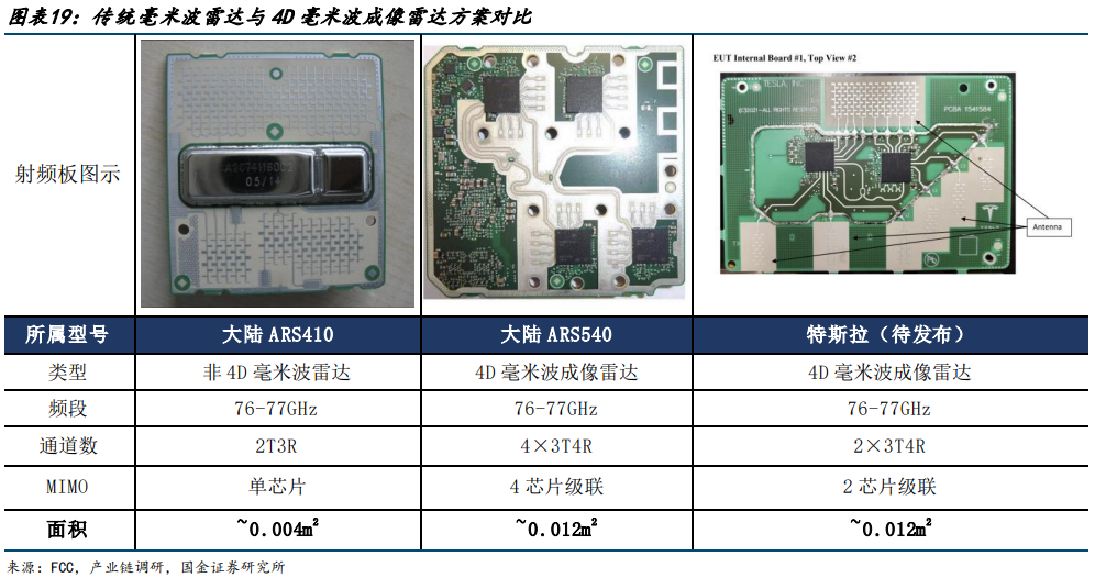
In summary, compared to traditional millimeter-wave radar, the PCB value of the 4D millimeter-wave radar RF board is expected to rise from 12 yuan to 60-100 yuan.
PCB changes of signal processing board
Generally, signal processing boards have high-speed processing requirements, so PCBs are mostly made of high-speed board materials. Due to the increase in signal processing capacity of 4D millimeter-wave imaging radar, the specifications of PCBs will also be upgraded accordingly. However, it is worth noting that due to the intervention of AI algorithms and the increase in data fusion, the signal processing function on millimeter-wave radar will be simplified, resulting in a reduction in the design and process complexity of signal processing boards. According to research, the signal processing board PCBs of the currently launched 4D millimeter-wave radar will be upgraded from 4 layers to 4-6 layers, and the board materials will also use Ultra Low Loss level. The corresponding PCB value will increase from 10 yuan/unit to 20 yuan/unit.

Note: The above content is collated from the Internet, and the copyright belongs to the original author. If there is any infringement, please contact us for deletion.