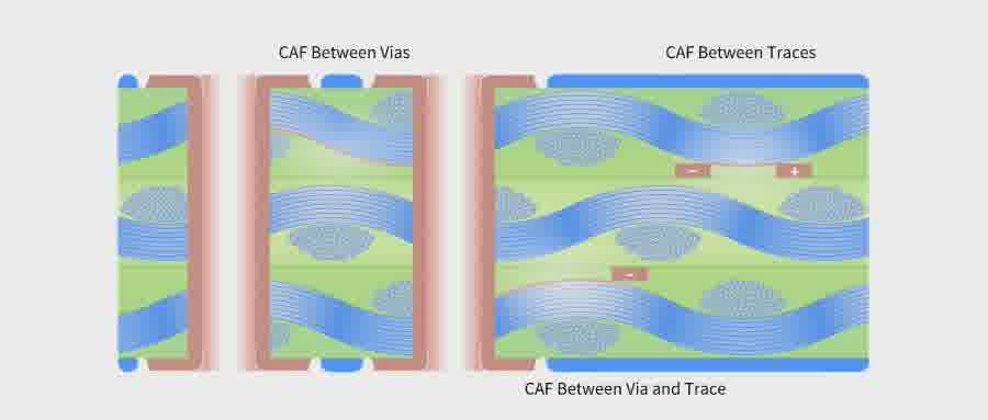
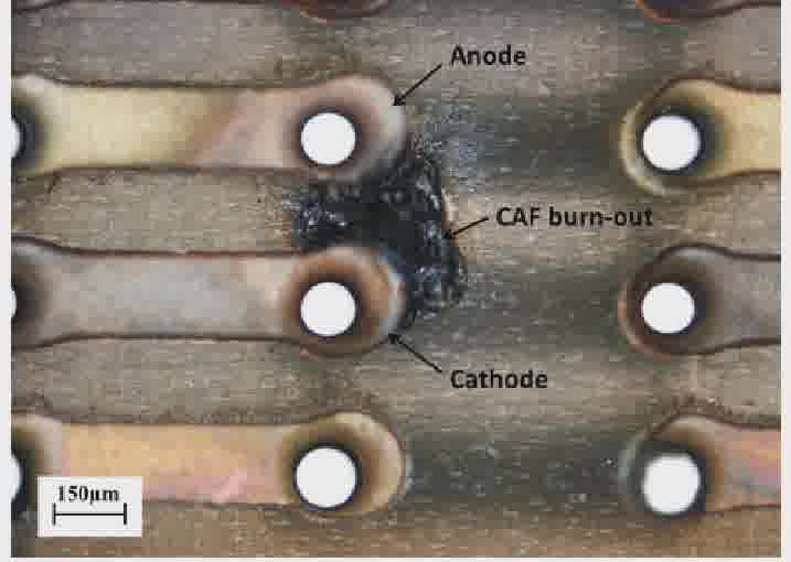
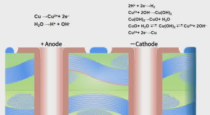
Conductive Anodic Filamentation (CAF) refers to an electrochemical failure mode occurring inside PCBs. Under high‑temperature and high‑humidity conditions and with an applied voltage potential difference, metal ions migrate along micro‑crack channels between glass fiber strands and trigger electrochemical reactions with metal salts, resulting in electrical leakage.
CAF can emerge between adjacent traces, between trace and via, as well as between vias. As circuit density rises, conductor spacing shrinks and via count increases, the migration path for CAF becomes shorter. Therefore, CAF has become a critical consideration in PCB reliability design.
Reduced insulation resistance: Conductive pathways formed by migrating copper ions drastically lower insulation resistance between adjacent conductors.
Increased leakage current: Electric current may flow through unintended paths, giving rise to higher leakage current.
Electrical short circuit: Hot‑humid environments accelerate CAF propagation, and in severe cases, permanent short‑circuits between conductors may occur.
Abnormal voltage: Sufficiently high leakage current pulls down circuit voltage and triggers malfunctions of electronic components.
Interfacial gaps between resin and glass fibers in glass‑reinforced substrates constitute the primary propagation channels for CAF. Such gaps may originate from multiple sources: excessive entrapped air during prepreg impregnation for copper‑clad laminates (CCL), excessive resin flow during lamination, improper drilling parameters or over‑reused, over‑ground drill bits that create rough, uneven via‑hole walls during PCB fabrication. All these defects provide potential pathways for CAF growth.
Water and electrolytes are essential for electrochemical reactions, and electrical potential difference accelerates reaction kinetics. In the initial CAF stage, moisture and metal salts accumulate inside gaps, which is greatly aggravated under high‑temperature, high‑humidity exposure. Once the PCB is powered on, the applied potential difference further speeds up electrochemical reactions and drives the secondary growth of CAF filaments.
Substrates with higher water absorption and lower pH are more susceptible to CAF. Higher temperature, higher humidity and higher operating voltage accelerate moisture uptake and electrochemical reactions, thus speeding up CAF propagation.
Fundamental CAF countermeasures aim to eliminate conditions for electrochemical corrosion: strengthen resin‑glass‑fiber bonding to minimize void formation, reduce substrate water absorption to prevent moisture entrapment in micro‑gaps, and adopt CAF‑resistant base materials.
Resin: Adopt high‑purity epoxy resin with low water absorption and superior thermal resistance. This reduces resin decomposition during lead‑free soldering, which would otherwise create substrate voids.
Glass fabric: Sufficient impregnation and bonding between resin and glass fabric improves CAF resistance. Glass fabrics with good fiber opening performance are preferred.
Copper foil: Excessively long or uneven copper profiles on copper foil increase CAF risk. Copper foil with uniform copper profiles shall be selected.
Lamination: Excessive resin flow or board‑edge whitening degrades CAF performance. Optimize lamination profiles according to substrate type and stack‑up construction.
Drilling: Excessive feed rate or heavily worn drill bits produce rough via‑hole walls. Recesses on hole walls trap metal‑salt solutions during wet chemical processes, which penetrate micro‑cracks and initiate CAF. Appropriate drilling parameters and fresh drill bits are required to guarantee hole quality.
Desmear: Residual smear degrades electroplating quality and raises CAF failure probability. Complete desmear is required.
 WeChat