
A Printed Circuit Board (PCB) motor is a general term for motors whose stators are fabricated using PCB technology. PCB‑wound stators have emerged as a viable alternative to conventional copper‑wire windings for axial‑flux motors, linear motors and planar motors.
Traditional motor‑stator winding consists of four core manufacturing steps: wire winding, coil insertion, potting, and epoxy curing.
Unlike conventional wound stators, PCB stators are fully designed for winding patterns and inter‑layer connections within EDA software. The resulting Gerber files are sent directly to a PCB manufacturer for production. Manufacturing of a PCB stator begins with circuit etching on copper‑clad laminates, followed by lamination with PP prepreg materials. Subsequent processes include outer‑layer drilling, hole metallization, surface finishing and profiling. Leveraging mature PCB production infrastructure, PCB stators deliver superior performance over traditional counterparts in parameter consistency, surface flatness and mechanical strength. End‑users receive finished stators ready for final assembly, eliminating extensive manual labour steps.
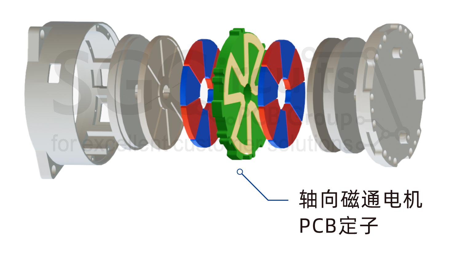
PCB stator for axial‑flux motor
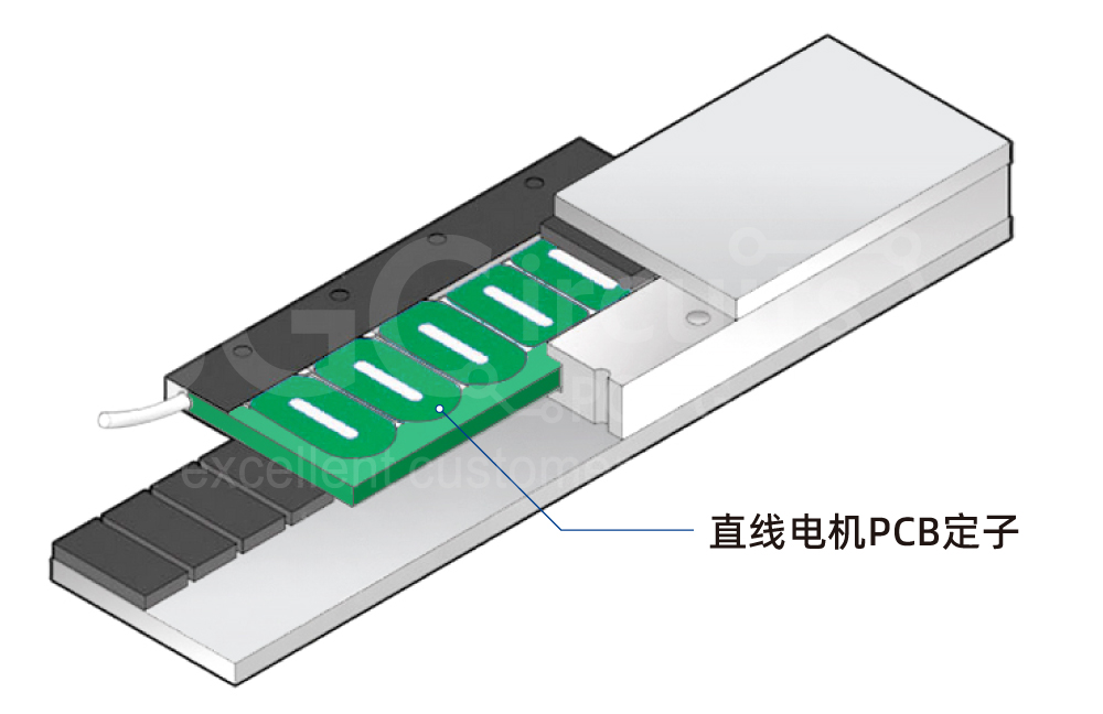
PCB Stator linear motor
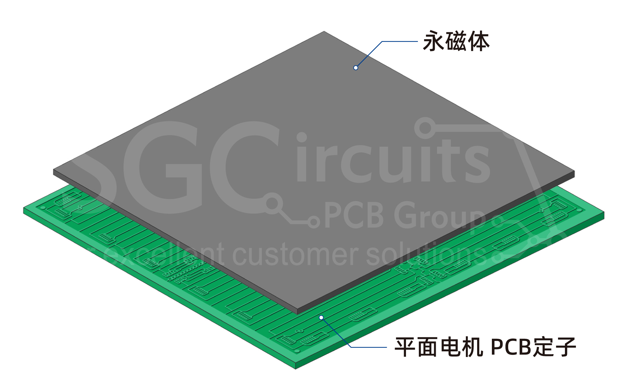
PCB Stator for planar motor
Stators built by PCB processes enable highly compact mechanical designs and significant overall motor miniaturization. Precision PCB manufacturing greatly improves winding accuracy and supports flexible winding topologies, translating to higher energy efficiency and reduced acoustic noise.
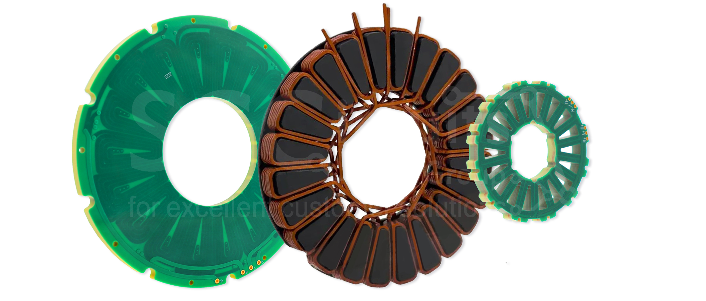
Conventional wound stator vs. Sunshine PCB‑designed stator
Historically, PCB motors were largely confined to low‑speed, low‑power applications such as hard‑disk drives (HDD), miniature cooling fans and thermal modules for precision instruments.
Advancements in multi‑layer heavy‑copper PCB, wide‑bandgap semiconductor drives and soft magnetic composite (SMC) materials have removed many historical technical bottlenecks. PCB motors are now expanding into higher‑power, demanding use‑cases including robotic actuators, aerospace motors, pumps and electric‑vehicle powertrain systems.
Compared with traditional motors, PCB motors offer distinct competitive advantages detailed below.
Weight Reduction: Iron‑free PCB stators achieve 30 %‑50 % weight saving relative to conventional motor stators.
Shorter Axial Dimension: The axial‑flux configuration cuts axial length by more than 40 %. For an EV water‑pump example, the axial dimension shrinks from 24.4 mm down to 14.4 mm.
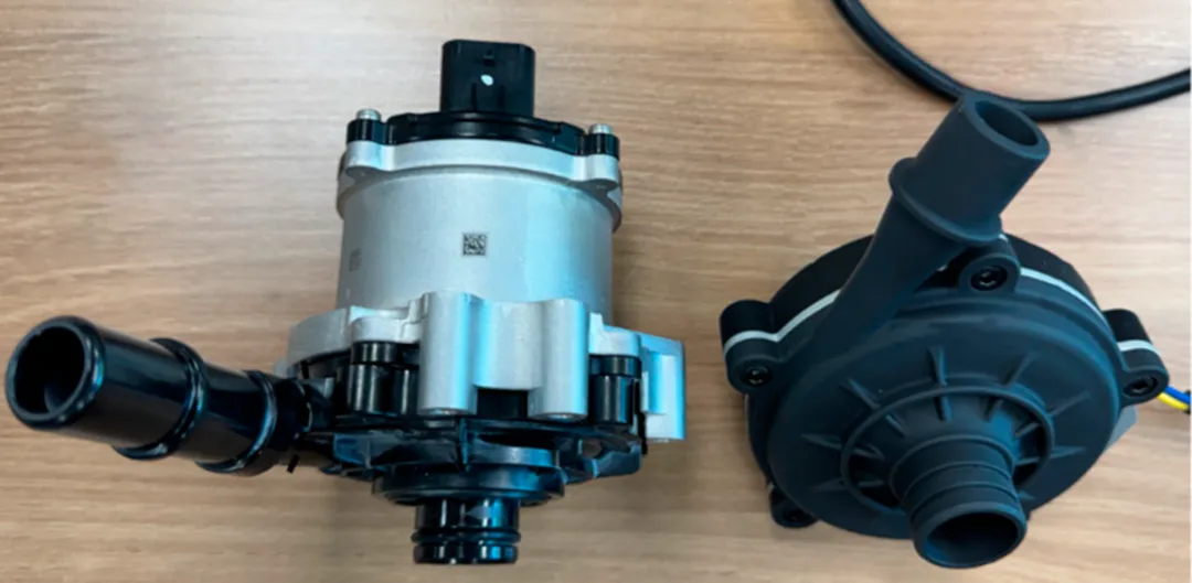
Conventional automotive water pump versus PCB‑motor water pump. Source: Design for Loss Reduction in a Compact AFPM Electric Water Pump with a PCB Motor, Energies 2025, 18, 2538
High Space Utilization: Ideal for space‑constrained equipment such as UAVs and robotic joints.
Zero Iron Loss: Iron‑free stator construction eliminates hysteresis and eddy‑current losses for improved efficiency.
Reduced Copper Loss: PCB stators support versatile winding patterns including concentrated, distributed and Litz‑type layouts, drastically shortening end‑winding length. Conductor width and circuit topologies can be fine‑tuned freely on the PCB stack‑up.
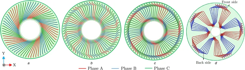
Source: A Comparative Analysis of Wave Winding Topologies and Performance Characteristics in Ultra‑thin Printed Circuit Board Axial‑Flux Permanent Magnet Machine, IET Electric Power Applications.)
Multiple PCB‑stator winding topologies:
a) Overlapping wave winding with parallel branches
b) Non‑overlapping concentric wave winding with radial wire‑exit
c) Overlapping concentric wave winding with radial wire‑exit
d) Single‑phase overlapping concentric wave winding distributed across PCB top and bottom layers.
Zero Cogging Torque: Iron‑free construction plus FR‑4 dielectric permeability close to air suppresses cogging torque almost completely. The motor runs more smoothly with lower acoustic noise, making it suitable for noise‑critical equipment in semiconductor and medical industries.
High Power Density: At the heart of the PCB stator is a multi‑layer PCB stack‑up. Photolithography forms planar copper windings directly on the substrate, achieving 60‑75 % copper fill factor between layers and delivering excellent power density.
Low Torque Ripple: PCB‑wound stators suppress harmonic components in back‑EMF and markedly mitigate torque ripple.
Ultra‑fast Dynamic Response: Iron‑free PCB stators are free from cogging effects, enabling millisecond‑range dynamic response for applications requiring frequent rapid start‑stop cycles.
High Vibration Resistance: Copper traces are fully embedded and cured within epoxy‑glass PCB substrates. There are no loose magnet wires, slot wedges or binding tapes. The monolithic structure delivers better mechanical‑shock endurance than wound‑coil motors.
Extended Service Life: PCB stators are constructed from copper, glass fabric and epoxy resin with thermally‑matched coefficients of thermal expansion. The whole laminate expands and contracts homogenously under temperature swing, minimizing thermal stress and boosting long‑term cyclic reliability.
Direct Liquid Cooling: 100 % of the stator surface can be immersed in oil or coolant to implement oil‑cooled or liquid‑cooled architectures, outperforming traditional motors that rely on limited contact area of jacket‑cooled housings.
Design Agility: Short PCB prototyping turnaround allows rapid iteration of winding topologies without hard‑tooling investment, lowering NRE and shortening development cycles.
Cost‑effective Mass Production: Established PCB automation infrastructure enables high‑volume output without purchasing dedicated winding or coil‑insertion machinery for motor manufacturers. The “form‑fit‑function” ready‑to‑assemble PCB stator reduces assembly steps and labour overhead, delivering favourable total‑cost‑of‑ownership at scale.
For inquiries about PCB‑motor solutions, please email salesteam@sunshinepcbmall.com, and our team will respond promptly.
 WeChat